
The flip-flop in electronic circuits is an electronic circuit that has 2 stable state that can be used to store binary information. The data stored can be altered by applying different inputs. Latches and flip-flops are the fundamental components of electronic systems that are employed in communications, computers and a variety of other systems. Both are utilized as storage devices for data.
It is the most fundamental memory element in the sequential system. First, let’s define the difference between latches and flip-flops.
Flip-Flop v/s Latch
The main distinction between a latch and flip-flop is the clocking or gating mechanism.
In Simple words. Flip Flaps are an edge-triggered device as well as a latch is triggers by level.
If you are confused about latch and flip-flop, you should look over this comprehensive article in which we discuss the differences between latch as well as flip Flop.
Let’s for instance, discuss SR latches as well as SR flip-flops. When you activate S then your output Q will become high while the Q’ will be Low. This is regardless of anything else. (This is an active-low circuit which means that active here is low. However, in the case of the active high circuit active, it would be high)
Flip-flops, on other hand is one of the synchronous circuits and is often referred to as the gated and clock SRL latch.
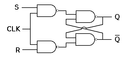
This circuit layout the output is altered (i.e. the data stored is altered) only when you provide the active signal for a clock. If not, even if S or the R is in use, the data will remain the same.
Let’s learn about the flip-flop in detail using the circuits and table.
Flip Flop Types
There are four types of flip-flops:
- SR Flip-Flop
- JK Flip-Flop
- D Flip-Flop
- T Flip-Flop
Let’s go through every flip-flop, one by one.
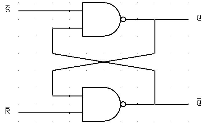
SR Flip Flop
It is the most used flip-flop of all. This circuit for flip-flops is very simple. It includes the set input (S) and an input for reset (R). In this circuit, if you set “S” as active, the output “Q” would be high and the output “Q ‘” will be low. When the outputs are set then it is the case that the circuit’s wiring is kept in place up to the point that “S” or “R” are high or the power is shut off.
As you can see in the previous paragraph, as you can see, it is the most simple and easy to grasp. Both outputs as illustrated earlier, are the inverse of the other. In the true table in the SR Flip-Flop is shown below.
| S | R | Q | Q’ |
| 0 | 0 | 0 | 1 |
| 0 | 1 | 0 | 1 |
| 1 | 0 | 1 | 0 |
| 1 | 1 | ∞ | ∞ |
JK Flip-Flop
Due to the non-definite state in the SR flip-flops, a flip-flop is needed in electronics. This flip-flop is called the JK flip-flop is an improvement over the SR flip-flop, where S=R=1 is not an issue.
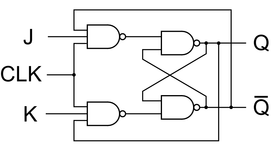
The input condition J=K=1 produces an output that reverses that output’s state. But the outputs are the same if you test the circuit on a real-world basis.
In simple terms, if J and K inputs to data are distinct (i.e. high as well as low) then the output Q is J’s value at the next edge of the clock. In the event that J is high and K are equally low no change is made. In the event that J as well as K are each high on the clock’s edge the output will change between states before switching to the other. JK Flip-Flops can serve as Reset or Set Flip-flops.
JK FF Truth Table:
| J | K | Q | Q’ |
| 0 | 0 | 0 | 0 |
| 0 | 1 | 0 | 0 |
| 1 | 0 | 0 | 1 |
| 1 | 1 | 0 | 1 |
| 0 | 0 | 1 | 1 |
| 0 | 1 | 1 | 0 |
| 1 | 0 | 1 | 1 |
| 1 | 1 | 1 | 0 |
D Flip-Flop
The flip-flop is an alternative that is extremely popular in electronic circuits. They are often used to control counters and shift registers as well as input sync.
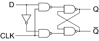
In D flip-flops their output can only be altered at the time of the clock’s edge and even if the input changes at other dates the output will remain unaffected.
Truth Table:
| Clock | D | Q | Q’ |
| ↓ » 0 | 0 | 0 | 1 |
| ↑ » 1 | 0 | 0 | 1 |
| ↓ » 0 | 1 | 0 | 1 |
| ↑ » 1 | 1 | 1 | 0 |
The state change in the output is determined by the time of day that the clock is on. Its output (Q) is the same as the input, and can only be changed at the edge of the clock.
T Flip-Flop
T flip-flop T flip-flop is similar to the JK flip-flop. They are basically single input versions of JK flip-flops. This modified version of JK is made by joining the inputs J with K. It only has one input and a clock input.
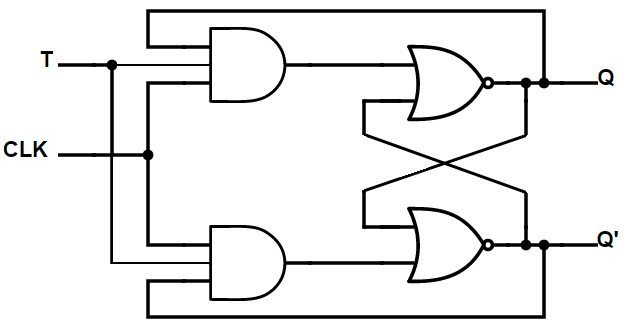
Flip-flops are known as T flip-flops due to their capability to work in conjunction with their states i.e. Toggle. This is why they are known as flip-flops that toggle.
Truth Table:
| T | Q | Q (t+1) |
| 0 | 0 | 0 |
| 1 | 0 | 1 |
| 0 | 1 | 1 |
| 1 | 1 | 0 |
Applications
These are the diverse types of flip-flops that are employed in electronic circuits for digital use and the uses of flip-flops are as follows.
We hope this article helps you in understanding the role of Flip-Flops in electronic devices.
If you are unsure about anything, you can ask in the comments section below or you can join the Forum for a chance to begin discussions with the group of electronics enthusiasts and engineers.
FAQs
Why is it Called Flip-flop in Digital Electronics?
A flip-flop is a kind of circuit that can be used to store and recall just one piece of data. Its name stems from its capability to “flip” or “flop” between two states of stability. By latching the value and changing it if triggered by the clock signal flip-flops can keep data for a period of time. They are known as flip-flops due to the fact that they can be found in two states that switch depending on an event that triggers them.
What Device is a Flip-flop?
The flip-flop is not a particular device however it is a term that is that refers to a collection consisting of circuits for sequential logic. These circuits, which are comprised of digital logic gates as well as other elements, can be built using various electronic elements such as transistors integrated circuits (ICs) or the programmable logic devices (PLDs).
What’s the Major Role of Flip-flops in Computer Electronics?
Flip-flops play an important function in electronic computers by acting as memory elements, which are used to store information about state, assuring the synchronization of clocks, enabling digital counting, and supporting control logic. They are crucial for the storage of data as well as coordination, sequencing and control in computers.
Also Read: